DC Generator Operation Principle and Construction
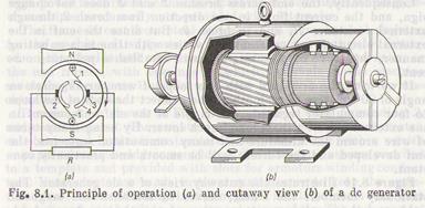
The simplest generator is a loop of a wire revolving in the magnetic field between poles N and S, as demonstrated in Fig. 4.1. The time-varying alternating emf induced in the loop forces the ac to flow through slip rings and brushes into an external load circuit. Such a machine is an ac generator. The conversion of ac to dc is accomplished through the use of a split-ring commutator. The commutator illustrated in Fig. 8.1 a
has two copper segments 4 connected to ends 1 of the loop. The commutator segments are fastened on the armature shaft and insulated from each other and from the shaft. Stationary brushes 2 and 3 connected to an external circuit rest on the commutator and slide on its surface.
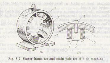
When the shaft carrying the loop of wire and segments begins to rotate, brushes 2 and 3 alternately contact each segment. The brushes are fixed in position so that they span the gaps between segments at the instant when the emf induced in the loop is zero. In this case, when the armature revolves, the alternating emf induced in the loop varies sinusoidally if the field is uniform, but each of the brushes makes contact with that segment and, thus, with that end of the conductor which at the given instant is under the pole of a definite polarity. Consequently, the emf across brushes 2 and 3 does not change sign, and the current flows in one direction from brush 2, through external resistance R, and to brush 3. But since the emf in the external circuit is not constant but varies with time in a pulsating manner, this wave of pulsating emf will establish a pulsating current. If we wind the armature with two loops of wire, arranged at an angle of 90° relative to each other, and connect the ends of the loops to four commutator segments, the ripple of the emf and current in the external circuit will become much lower. By using many turns of wire around the armature and many commutator segments, the emf developed and the current will be smooth and practically constant. Figure 8.1b illustrates the cutaway view of a dc generator. The stationary member, the stator, serves to establish the magnetic field, and the revolving member, the rotor, is the armature intended to generate the emf. The stator depicted in Fig. 8.2a consists of frame 3, or yoke, main field poles 1, and commutating (intermediate) field poles 2. The main pole illustrated in Fig. 8.2b is an electromagnet producing the magnetic flux. It consists of core 4, field coil 6, and pole shoe 7. The main pole is fastened to the frame 3 with bolt 5. The pole core is cast from steel and has an oval shape in cross section. The field coil consists of many turns of insulated copper wire wound on the core. The coils of all poles are connected in series to form the field winding. The current flowing through the winding produces the magnetic flux. The pole shoe secures the field coil on the core and provides for the uniform distribution of the magnetic flux under the pole. It is given such a shape that the air gap between the pole and armature is the same over the entire length of the pole arc. Commutating poles, or interpoles, also carry coils on their cores. Interpoles are fixed between the main poles; their number can be equal to or half the number of main poles. They are fitted on
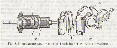
high-power machines to eliminate sparking at the brushes. Small-power machines are usually not provided with interpoles. The frame is cast from steel and serves as a mechanical skeleton* for the machine. It supports the main and commutating poles fastened on the inside and also carries at its end faces the end bells, or the end frames, with bearings in which the shaft of the machine-revolves. The frame is made with cast feet for mounting the machine on supports. The armature shown in Fig. 8.3a consists of core 1, winding 2, and commutator 3. The armature core is a cylinder built of electrical-sheet steel laminations insulated from each other with a vanish, or paper to reduce eddy-current losses. Steel laminations are punched to a template and provided with slots for armature winding conductors. Vent ducts are made in the armature core to keep the armature cool. The winding is thoroughly insulated from the core-and fastened in the slots by nonmagnetic wedges. The end connections are secured to the supporting rings with a band wire. All coils of the winding fitted on the armature are connected in series to form a closed circuit and soldered to commutator segments. The commutator is a cylinder consisting of commutator bars, which are wedge-shaped (dovetailed) segments of hard-drawn copper insulated from each other and from the commutator sleeve by thin strips of micanite. Each commutator bar is held in place by clamping its dovetailed portion between the V-shaped projections on the sleeve and the ring, the latter being bolted to the sleeve by cap screws. The commutator is the most complex part from the design viewpoint. Besides, in some respects, it is the most important part of a dc machine. The surface of the collector must be exactly cylindrical to avoid wobble and sparking at the brushes. The brushes that collect current and pass it to an external circuit «can be made of the graphite, carbon-graphite, and bronze-graphite types. High-voltage machines use graphite brushes that have a high contact resistance; low-voltage machines operate with bronze-graphite brushes. Fig. 8.3b illustrates a brush holder. Brush 4 inserted into the brush box is held up against the commutator surface by springs 5. Each brush holder can contain a few brushes connected in parallel. Brush holders have openings for fastening them on brush-holder studs which, in turn, are made fast to a brush rocker arm and insulated from it by conductive washers and sleeves. The number of brush holders is commonly equal to the number of poles. The rocker arm is set up on the end shield of a small and a medium machine or fitted on the frame of a large machine. The rocker arm can be swayed to change the position of brushes relative to poles. It is commonly held in such a position as to enable the brushes to be in alignment with the axes of main field poles.
|