DC Generator Characteristics
The characteristics of a generator define its performance and represent the relation between its main parameters such as the emf E in the armature winding, terminal voltage V, armature current I, field current If, and rotational speed n of the armature. The characteristics determine the relation between any of the two parameters, with the rest of the parameters kept invariable. These relations are not identical for the different types of generators. The readings obtained to plot any characteristics must be taken when the machine runs at a constant speed because changes in the speed change all the characteristics. The no-load characteristics is the plot of armature emf as a function of field current in the open-circuit conditions and at a constant speed.
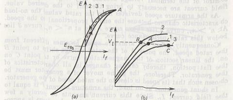
Fig. 8.12. No-load characteristics of a separately excited generator, representing the emf E versus field current If during the complete cycle of magnetization (a) and E versus If during changes in the armature speed (b)
In separately excited generators running at no load, the armature current is zero. Since the emf generated in the armature winding is E = cnΦ, then at a constant speed the emf will be proportional to the magnetic flux. Therefore, the no-load characteristic plotted to a changed scale represent the magnetization curve of the machine. At If = 0, the magnetic circuit (mainly the yoke) retains a certain residual flux Φres which induces the emf Eres in the armature winding (Fig. 8.12a). This emf reaches 2 to 5% of the rated voltage. As the field current grows, so do the magnetic flux and the emf induced in the armature winding. Thus, at a constant rate of rise of the current If, the emf increases (curve 1). If, after plotting the ascending branch, we gradually reduce the field current If from the point A, the emf will start decreasing, but the iron magnetization will cause the descending branch (curve 2) to pass slightly above the ascending branch. Changing If, both in magnitude and in direction, allows us to plot the entire hysteretic cycle of iron magnetization, demagnetization, and saturation. In essence, initial curve 1 and downward sloping curve 2 of the magnetic characteristic diverge very insignificantly, and average curve 3 is taken as the basic magnetization curve. Figure 8.12b presents the no-load characteristics of E plotted versus If at different speeds of the generator armature. Curve 1 corresponds to rated speed nr entered into the generator certificate. For all machines of the ordinary type, the rated voltage point 1 lies on the bend of the magnetization curve, which corresponds to the most optimum operating and control characteristics of the generator. The choice of this point on the linear section of the curve leads to sharp variations in the load terminal voltage because even small fluctuations of the mmf heavily change the emf. The choice of this point on the flat portion of the curve limits the range of control of the terminal voltage because very large changes in the field current are necessary to bring the emf to the desired value. As the armature speed deviates from the rated value, the no-load characteristic changes because the emf is proportional to the speed. At n' Z> nr, curve 2 lies above curve 1 and at n" < nr, curve 3 lies below this rated performance curve. Consequently, when the armature speed becomes different from the rated speed, the point A of the rated voltage shifts to point В on the linear section of the magnetization curve or to point С on the flat portion, thereby causing changes in all characteristics of the generator. Therefore, the prime mover of a generator must be chosen such that its speed is close to the rated speed of the generator. In shunt generators at no load, the armature current I is equal to the field current If. Since this current amounts to merely a few percent of the rated current, the no-load terminal voltage is approximately equal to the generator emf, so the no-load characteristic of this type of generator is essentially similar to that of the separately excited generator. But it is impossible to plot the entire cycle of magnetization in a shunt generator because the reversed field current will oppose the residual flux and the generator will riot be brought to excitation. For a series generator, the no-load characteristic has no meaning because at no load the current in the armature winding and field winding is zero. For this characteristic to be plotted, the series generator must be run as a separately excited generator by connecting its field winding to an external source of energy. The no-load characteristic of a compound generator is identical to that for a shunt generator. The external characteristic represents the terminal voltage laid on the y -axisas a function of the load current plotted along the x -axis. This characteristic corresponds to the natural operating conditions of the machine, which is run at constant (rated) speed with the field winding resistance Rf held constant too. For separately excited generators, the field current If is also held invariable of a constant Rf. The external characteristics of this
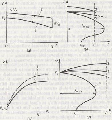
Fig. 8.13. External characteristics of a separately excited generator (a), shunt generator (b), series generator (c), and compound generator {d)
type of generator are shown in Fig. 8.13a. Curve 1 represents the dropping-voltage (drooping) characteristic that corresponds to the field current at which the generator voltage is equal to the no-load rated voltage. An increase in the load, i.e. armature current I, leads to an increase in both the voltage drop across the armature winding resistance and the demagnetizing effect of armature reaction, with the result that the voltage falls off. When the load increases from zero to the rated value, the drop in terminal voltage becomes equal to ΔVd. Curve 2 represents the rising-voltage characteristic corresponding to such a field current that the terminal voltage is equal to the rated value at the rated load. When the load (armature current) decreases, the voltage rises because of the lower armature reaction and decreased voltage drop across the armature winding resistance and the brush contacts. When the load drops from the rated value to zero, the terminal voltage rises by ΔVr. But the voltage rise will be smaller than the voltage drop because the demagnetizing action of armature reaction grows with a decrease in the amount of iron saturation. In shunt generators, the field current does not remain constant at a constant Rf since it depends on the terminal voltage which varies with the load. In separately excited generators, an increased load causes the voltage to fall off as the result of the armature reaction and the voltage drop across the generator resistance (curve 1 in Fig. 8.13b). The drop in voltage of a shunt generator leads to a decrease in both the field current and the magnetic flux, which then reduce the voltage still more heavily. The terminal voltage of this type of generator thus drops to a greater extent with the increasing load than is the case for a separately excited generator. A decrease in the external load resistance increases the current to a certain value I max which is not in excess of 2 to 2.5 times the rated current. As the external resistance continues to decrease further, the current falls off and becomes lower than the rated value in short-circuit conditions. A lower load resistance leads to a decrease in the field current since the generator voltage falls off. If the field current drops so heavily that it causes the generator demagnetization, the emf begins to decrease at a greater rate than the load resistance and the armature current then diminishes. With the shunt generator shorted out, the current If is equal to zero and the field winding does not produce the magnetic flux. The field winding will then have a small emf Eres due to the residual current, so the short-circuit current I sc will also be small. Despite a small value of the steady short-circuit current, one cannot say for sure that the short-circuit conditions are not hazardous to this type of generator. In the event of a short circuit on such a generator, the field current cannot instantly drop to zero, as cannot do the magnetic flux. Therefore, at the instant of a short circuit the armature winding will induce a high emf forcing a current to flow that is several times the rated current. The intensive brush sparking that results may convert to a round discharge that may cause the machine failure. The rising characteristic of a shunt generator has the same shape as that for a separately excited generator (curve 3 in Fig. 8.13 b). In a series generator, the field current If is equal to armature current I and at no load, when I = 0, the armature winding will have an emf Eres, induced by the flux of residual magnetism (Fig. 8.13 c). With an increase of a load, the field current begins to grow, and so does the emf (curve 1). The terminal voltage of the generator under load is smaller than the emf due to the voltage drop across the generator resistance and armature reaction (curve 2). In a series generator, the voltage thus varies sharply with the load, for which reason this type of generator has no gained favor. The compound generator can have its parallel and series windings connected in aiding and in opposition. With the aiding connection of the field windings (cumulative compounding), the resultant mmf producing the flux is the sum of the emfs of the two windings. With the windings connected on opposition (differential compounding), the resultant mmf is the difference between these mmfs. As the load increses, the generator voltage falls off because of the armature reaction and voltage drop across the generator resistance. But then the current in the series field winding begins to rise. That is why, with the field windings connected in aiding relationship, an increase of load will cause the magnetic flux and the emf in the armature winding to grow. If the emf rises by a value equal to a decrease of the generator voltage due to the voltage drop across the generator resistance and armature reaction, then the generator builds up a practically constant voltage when the load changes from zero to the rated value (curve 1). Such a generator, called flat-compounded, does not call for field current adjustment with load changes. If the series winding has a smaller number of turns than that used in flat compounding, the emf will rise with load to a lesser extent and will not build up to the no-load value (curve 2). This is an undercompounded machine. If the series winding has a larger number of turns than that used in a flat-compounded generator, the generator is said to be overcompounded, and its terminal voltage will grow with the load (cuve 3). In a differentially compounded generator, the external characteristic is similar to that for a shunt generator (curve 4), but the maximum current Imax and short-cicuit current Isc in the former will be smaller than those in the latter because of the demagnetizing effect of the series winding mmf. Most popular are flat-compounded machines and also overcompounded machines which make it possible to compensate for the voltage drop in the line and connecting leads and thus to keep the voltage across the load constant with current changes. Differential compound generators do not provide for constant voltage and have limited applications, only where it is necessary to reduce short-cicuit currents, for example, in electric welding. The control characteristic of a generator represents the field current plotted versus load current at a constant terminal voltage. This characteristic shows the extent to which the field current should be varied to keep the terminal voltage constant with changes in the load current. In separately excited generators and shunt generators, the field «current should be raised with load to compensate for the voltage -drop across the machine resistance and the demagnetizing action of the armature flux. In flat-compounded generators, the voltage does not vary with load, so there is no need to control the field current.
|