MILLING OPERATIONS
Purpose of the work. To study the construction of milling machine-tools with horizontal and vertical spindles; to make acquaintance with the types of milling cutters; to master the necessary setups according to a given milling conditions; to determine the main (machine) time in milling. Theory. Milling is the process of producing machined surfaces by progressively removing a predetermined amount of material from a workpiece which is fed to a rotating milling cutter. Milling cutters are often referred to as multitooth tool. The main movement in this case is the rotation of the milling cutter. Feed (longitudinal, transverse (cross) and vertical) is imparted to the workpiece, mounted on the table. Milling is a high-productive process to machine flat (horizontal, vertical and inclined), shaped surfaces, grooves, shoulders etc. There is a number of different milling cutters, each one designed for a certain purpose (Fig. 6.6): plain or slab cutters (a), face mills (b), side milling cutters (c), end mills (d), angle (e), keyway (f) and form mills (g, h) are some of the more common ones. By the teeth contour and girding method the milled (sharp-cut) and form-relieved milling cutters are distinguished (Fig. 6.6 i, j). Teeth of a form-relieved cutter retain their cutting edge contour in radial section while sharpening along the front plane. The milling cutters may be either solid (single-piece) mainly of high-speed steel or with inserted teeth. The last cutters are often made of carbon steel. Inserted teeth of high-speed steel, tungsten or titanium carbides and ceramic may be fastened in special holders, brazed or screwed down to the cutter.
Fig. 6.6. Milling cutters
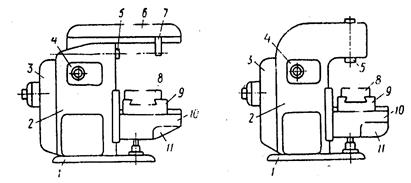
Horizontal and vertical knee-and-column milling machines are depicted in Fig. 6.7. They have a base 1, a column 2, an electric motor, equipped with a belt transmission 3, a spindle speed gear box 4, a horizontal or vertical spindle 5, an overarm 6, an outer arbor support 7, a table for the workpiece mounting 8, a slide 9, a knee 10 and a feed gear box 11.
Fig. 6.7. Horizontal (a) and vertical (b) knee and column milling machines
A cutting regime is determined by cutting speed V, m/min, feed and depth of cut t, mm. The feed may be determined as: feed per minute Sm – surface mm per minute, traveled by the cutting edge of a cutter; feed per revolution Sr – travel of a workpiece per one revolution of a spindle, mm, and feed per tooth SZ, mm. The feeds are mutually related to each other: Sm=Sr ×n = SZ ×Zn where n is revolutions per minute of a spindle; Z is teeth number of a cutter. Feed per minute determines the machining productivity, while feed per tooth characterizes tooth loading and, thus, durability of a milling cutter. The milling productivity is estimated by a number of articles Q, machined per certain period of time T (month, shift, hour); Q=T/Tk where Tk is time, required to machine one article, min.
The machine (technological) time Tm, mm, (the direct manufacturing time, spent in the process of machining) is the main component of the total time, required to manufacture an article: Tm=L×I /Sm where L is calculated length of a workpiece, mm i is number of passes.
The calculated length (Fig. 6.8) L=l1+l+l2
where 11 is cutting-in distance of a milling cutter, mm; 1 is true length of the workpiece, mm; 12 is overtravel of the milling cutter, mm (is taken as 2...5 mm).
Fig. 6.8. Determination of calculated length of a workpiece in plane (a) and face (b) milling
The cutting-in distance 11, mm, is determined in plain milling as follows:
in symmetric face milling respectively:
where D is diameter of the milling cutter, mm; t is depth of cut, mm; B is width of work surface, mm.
|