Current Transformer
Differential current Protection UNIT 8 PHASEPROTECTION(Merz Price circuit)
AIM OF THE UNIT:- to understand phaseprotection (Merz Price circuit)
TASKS 1 Do your best to answer the brainstorming question. 2 Read the text for general understanding. 3 Make up questions to the text. 4 Find the sentences with the new words in the text. Give the Kazakh or Russian equivalents of the words. 5 Write sentences with the new vocabulary. 6 Make up exercises as in the UNIT 2 (Master`s degree students individual work with the teacher) page 210 (exercises for better remembering the topic). 7 Speak on the topic. Given schemes will help you to remember and understand the topic. 8 Find more information about the topic and make up a project work on the topic.
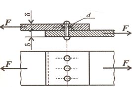
Circuit protects against faults between phases, or from individual phase to ground faults. Connections are shown for protection of a single phase, a three-phase system would require the same circuit per phase. Two current transformers (CT) are located at each end of the feeder distribution line:
CT 2 monitors the current into the distribution system. Secondary windings of each current transformer are connected via two relay coils; these windings are formed in the opposite direction. When current flows through the feeder, there is equal current in both coils; the induced EMF is balanced, so no current flows. If a fault develops in the feeder line, current CT 1 flows (but not CT 2), thereby creating an unbalanced condition.Current flow in either of the coils opens the contacts and disconnects the feeder line at both ends. Breakers/contactors Breakers (sometimes referred to as contactors) are used in power generation systems for connecting feeder lines to busbars and for interconnecting various busbars. Unlike conventional circuit-breakers, these devices can be tripped on or off remotely. They have several heavy-duty main contacts to switch power and a number of auxiliary contacts for the control of other circuits, e.g. warning lights, relays etc. The breaker is closed by an external control switch via contacts A; the coil remains energized via contacts B to ground. With the coil energized, the main and auxiliary contacts are closed and the spring is compressed. Contacts A latch the breaker closed, assisted by the permanent magnet. When a trip signal is applied (either by a fault condition or manual selection) current flows to ground in the opposite direction. The spring assists the reversed electromagnetic field and this breaks the permanent magnet latch. A Zener diode suppresses arcing of coil current across the contacts.
|


 CT 1 monitors the current output from the generator