Transformer Operation
In the no-load operation of a transformer, its secondary is open and no current flows in this winding. But the primary carries a no-load (open-circuit) current Io which is only a fraction of the current in this winding when the transformer operates into the rated load. The no-load magnetomotive force (mmf) I0w1 produces an alternating magnetic flux which passes through the magnetic circuit and induces emfs in the primary and the secondary. The varying magnetic flux that links any turn induces an emf in this turn, which is equal in magnitude and opposite in sign to the magnetic flux at any moment of time. If the flux changes in value by dΦ in time d t, the emf induced in the turn is e = — dΦ / d t. If dΦ is in webers and d t in seconds, the emf induced is in volts. The negative sign indicates the direction of emf at which the induced current in the turn produces the magnetic flux that opposes any changes in the main magnetic flux. Thus, if the main flux grows in magnitude (dΦ is positive in sign), then the emf-induced current sets up the magnetic flux opposite in direction to the main flux. When the main flux decreases (dΦ is negative), the current due to the emf produces the magnetic flux in the direction of the main flux. Transformer windings usually have a large number of turns w1 and w2. In each turn of either of the two windings, the magnetic flux induces the same emf, since this flux links all the turns of the two windings. Therefore, the emf of each winding is equal to the sum of emf in all the turns, i.e. it is equal to the product of the number of turns by the emf induced in one turn: e1 = — w1 dΦ /dt and e2 = — w2 dΦ /dt. Practically, the flux in the magnetic circuit always varies with time sinusoidally, Φ = Φ т sin ωt, if the voltage impressed on the primary is sinusoidal. The sine wave of the magnetic flux induces the sine waves of emfs in the primary and secondary. These emfs become larger in magnitude as the rate of change of the flux increases. In the interval from 0 to t1 the magnetic flux grows (dΦ > 0), therefore the emfs in the windings are negative. The flux changes most rapidly at the instant t = 0, while at the instant t1 the flux does not undergo changes. So, at t = 0, the emfs are maximum, whereas at tx they are equal to zero.
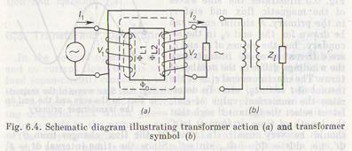
So, the maximum rate of change of the flux is (dΦ/d t)m = Φ '/t' — (Φm sin ωt')/t' = Φm ω and the maximum emf of the primary is Elm = w1 (dΦ/d t)m = w1 Φm ω = 2πfw1 Φm. The effective value of emf in the primary is E1 = E1m/ Because no current flows in the secondary at no-load, the voltage across its terminals is equal to the emf, V2 = E2. The primary carries a weak no-load current, so the voltage across this winding insignificantly differs from the emf, V1≈ Е1. The ratio of the terminal voltages V1 and V2 in the no-load operation is known as the transformation ratio, or turn ratio: n = V1/V2 = E1/E2 = w1/w2; V1 = V2w1/w2=nV2. Consequently, if the primary and the secondary have different numbers of turns, the voltage Vx in the primary connected to an ac circuit differs from V2 induced in the secondary. If the secondary carries a load (Fig. 6.4a), a current I2 will flow through the secondary circuit; the current I1 in the primary can be given as the phasor sum of the no-load current and the load current. There is no electrical connection between the primary and the secondary of an ordinary transformer. But it should be kept in mind that the inductive coupling between these windings causes a change in I1 with a change in I2. If the current in the secondary grows, the current in the primary grows accordingly. On the contrary, with a decrease in I2, the current I1 decreases. If the secondary is open, the current I2 is zero and the current in the primary drops to a small no-load current I0.
The primary and the secondary being loaded, numerically unequal currents flow through the two windings. Neglecting the power loss in the transformer, the power given up to a load, V2I2, is equal to the power drawn from the supply circuit, V1I1, i.e. V2I2 = V1I1, I2/I1 = V1/V2 = n; and I2 = nI1. Leaving out of consideration the voltage drop across the resistance of the primary, it is safe to assume, as we have shown earlier, that the absolute values of impressed voltage V1 and the values of emf E1 balancing out V1 are numerically equal, whatever the load on the transformer: V1 = E1. This equality allows us to conclude that at an invariable value of the applied voltage V1, the emf E1 induced in the primary at any load will be approximately invariable too. Since the emf E1 depends on the magnetic flux Φ т, then the flux in the magnetic circuit will also be approximately invariable despite the changes in the load. So, at a steady impressed voltage, the amplitude of the magnetic flux in the transformer core will practically be the same at any load. The current I1 flowing in the secondary of the loaded transformer produces the magnetic flux which, by Lenz's law, opposes the magnetic flux in the core and tends to reduce it. In order for the resultant magnetic flux in the core to remain invariable, the opposing magnetic flux in the secondary must be balanced out by the magnetic flux in the primary. Consequently, with an increase of current through the secondary, the opposing magnetic flux in this winding grows. In turn, both the current I1 and the flux induced by this current in the primary grow too. Since the primary flux counterbalances the secondary flux, the resultant flux in the core remains invariable. In a step-down transformer, the primary voltage V1 is n times higher than the secondary voltage V2, therefore the secondary current I 2 is n times as high as I1. The opposite is true in a step-up transformer. So, a high-voltage winding carries a lower current than a low-voltage winding. The former has much more turns of wire of a smaller cross section than the latter. When a transformer supplies power to a load, the currents flowing through the primary and the secondary induce leakage fluxes ΦL1 and ΦL2. Each of these fluxes threads only the turns of the winding that carries the current inducing this flux. The leakage fluxes are always much lower than the main flux Φm closing on itself through the magnetic circuit (core) because they return through air and insulation without linking the windings. These fluxes induce leakage emfs in the windings, which slightly change the secondary voltage. The symbol of a transformer is shown in Fig. 6.4fe, where Z1 denotes the load impedance. In order to avoid installing a separate transformer for each operating voltage, it is advantageous that a transformer should comprise a few secondary windings with different numbers of turns. Such a multiwinding transformer is widely used in radio receivers, television receivers, amplifiers, and other devices whose elements require several values of operating voltages. The turn ratio which is approximately equal to the transformation ratio is a function of output and input voltages: w2/w1=V2/V1; w3/w1=V3/V1, etc. The primary current is the sum of secondary currents: I1 = I2V2/V1+I3V3/V1+ …. A change in the current through any secondary causes a corresponding change in the current through the primary. This, in turn, changes voltages across all the secondaries. In other words, the voltage in a secondary depends on the current through both this secondary and any other secondary.
|
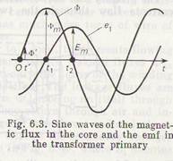 In the interval from t1 to t2, the magnetic flux decays (dΦ < 0), so the induced emfs are positive. It is thus possible to determine the emfs in the primary and the secondary at every instant of time. Fig. 6.3 illustrates the sine waves of the magnetic flux and emf e1 in the primary. A similar curve can be drawn for the emf e2 in the secondary, but the values of e1 and e2 are different at every instant since the windings differ in the number of turns. The maximum emf e1 is at the instant of t = 0, t2, etc. To determine the numerical value of emf, let us select the instant t' such that the length of time d t from 0 to t' should be very small. In time d t the flux changes from 0 to Φ', i.e. dΦ = Φ' = Φm sin ωt'. Since the time interval dt = t' is very small, the angle ωt' is very small too, in which case the following approximate equation is valid: sin ωt' = ωt'.
 =4.44 w1 f Φm because 2π