Synchronous Generator Principle and Construction Features
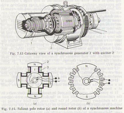
In synchronous machines, the speed of a rotor is equal to the rotational speed of a stator field and, therefore, it is a function of both the frequency of the line current and the number of pairs of poles n = 60 f/p, where f = pn/60. ' A synchronous machine is reversible, as is any other electric machine, i.e. it can run as a motor and as a generator. The prime mover of a synchronous generator is a hydroturbine or a steam turbine, or an internal combustion engine. The field winding of the generator commonly receives power from an exciter which is a dc generator fitted on the shaft of the generating unit. The capacity of the exciter is small in the order of 1 to 5% of the rated capacity of the generator. In small machine the field windings are often fed from an ac supply line via a semiconductor rectifier. In Sec. 4.1 we described in detail the principle of the simplified generator represented in Fig. 4.1 as a loop of wire revolving in the magnetic field of a permanent magnet or in the field excited by the current of the field winding placed on the poles N and S of the stator. Let us return to Fig. 4.1 and recall some of the main points of the operation principle and construction of the generator. The revolving loop of wire with its ends connected to slip rings 3 represents the armature winding. This loop of wire, slip rings revolving with the loop, stationary brushes placed on the rings, and the external circuit connected to the brushes to supply a load form a closed circuit through which a current will flow by the action of the emf generated in the loop as conductors 1 and 2 cut the magnetic flux. The emf continuously changes in magnitude depending on the position of the loop in the magnetic field. In position III, the conductors cut the largest number of magnetic lines in a unit of time and the emf in the loop is the highest. As the loop continues to revolve, the conductors cut a smaller number of magnetic lines per unit time. When the loop turns through 90° from position III to position V, conductors 1 and 2 rotate in the direction of magnetic lines. They, thus, do not cut the magnetic lines and the emf in the loop is zero. As the loop turns further, the emf reverses its direction and reaches the peak when the loop swings through 90° from position V to position VII. If the magnetic field between the poles N and S is uniform, the emf wave is sinusoidal. During one period, as the loop turns by one revolution, the emf undergoes one complete cycle of changes. If the loop driven by a prime mover revolves at a constant speed n in a minute, the alternating emf induced in the loop repeats itself at a frequency f = n /60. It is possible to generate the emf in conductors as they move in the stationary magnetic field and as the field revolves with respect to the stationary conductors. In the first case, the field winding intended to excite the magnetic field is on the stator, and the armature winding where the field induces the emf is on the rotor. In the second case, the armature is stationary, while the field winding revolves on the rotor. In the text above, we considered the action of the synchronous generator with the stationary field winding (stationary poles) and the revolving armature which gives up its generated energy to a load through sliding contacts formed by slip rings and brushes. The sliding contact in a high-power circuit is responsible for heavy power losses and is completely unacceptable at high voltages. Therefore, this type of generator is designed for low powers, up to 15 kVA, at voltages up to 380/220 V. The second type of synchronous generator with a stationary armature and a revolving field has received the widest application. The field winding here consists of several series-connected coils arranged on the poles of the rotor. The exciter (dc generator) fitted on the common shaft supplies the field current to the field winding through brushes and slip rings. Figure 7.13 illustrates the general view of a synchronous generator with an exciter. The stator of a synchronous generator is similar
in construction to that of an induction machine. The rotor of a synchronous generator can have salient poles or nonsalient poles that do not project out from the surface of the core. The first rotor is known as a salient pole rotor, and the second as a round, or a cylindrical, or a nonsalient pole, rotor. In slow-speed machines (with a large number of poles), the rotor has salient poles uniformly located around its circumference (Fig. 7.14a). The pole consists of core 1, pole piece 2, and coil 3 the field winding. The prime movers for salient pole generators are commonly hydro-turbines which are slow-speed sources of mechanical power. The mechanical strength of a salient pole rotor is not sufficient to stand up to high speeds, for which reason high-speed machines are built with round rotors (Fig. 7.14b). The core of such a rotor is usually a one-piece forging with slots milled on its surface. After completing the field winding on the rotor, the coils are fastened in the slots by wedges driven into the slots and the end connections of the winding are secured with banding wire applied on the face portions of the rotor. Such a rugged construction endures heavy loads arising at high speeds. The prime movers of nonsalient pole machines are usually steam turbines which run at high speeds.
|