Measuring the time interval (period) of info signal
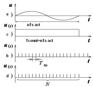
In this mode, the comparison of the researched signal measured period Т s model with a time interval. The signal is going to the input 2 electronic frequency counter (Figure. 1, key is in position 2) and then after appropriate transformations in blocks (7) (8) and (9) via a control unit (10) is fed to the second input selector (4). In block (10) of the test signal is formed by a rectangular gate pulse, the duration of which coincides with the period of the signal or a multiple thereof. The voltage from the standard frequency crystal oscillator (5) through a frequency multiplier (6), switch (2) (the position of key switch - "2"), the inverter (3) and then fed to a first input selector of the time. Stress diagram illustrating the operation mode of electronic frequency counter meter measurement period are shown in Figure 3. They show that the period of the signal is given by:
where Т m – the period of the signal model (time of marking); N – number of marks received by the counting unit electronic frequency counter; n – the factor period (for the given case is n = 1).
Calculation time is given by:
The result is displayed on electronic frequency counter, usually represented in units of the selected "mark time" (ms or µs). The situation with the decimal point depends on the value of the multiplier period, and the numerical values of the period of temporary tags. Accuracy of measurement period Т s act consists of three components: the error of measure, conversion and comparison. The error measure is due to the relative instability of the crystal frequency δqg = 5·(10-8÷10-12). The error is caused by the transformation δt mainly the ratio of the voltage signal and noise that affects the formation of the control pulse and is determined from the expression (Simpson's formula):
where n – number of periods of the measured signal; U n – the average value of the voltage noise; U s – the average value of the voltage signal. If The error is caused by an error of discrete comparisons. Absolute and relative error respectively,
The total relative error is given by:
To select the best performance in terms of minimizing the error, we consider the following example.
Example. Let the measured signal frequency is ƒ;s res = 100 Hz, (Т сount = 10-2 s), by the same frequency meter. To define: ∆ N, δ N, to choose n, T m and record the measurement result. Solution. Choose the timestamps (usually a minimum value), Т m = 0,1µs = 10-7 s. Given the limitations on the counting value of the multiplier block of n signal period:
Since 10 < n <102, then the multiplier period take n = 10. Write down the measurement period on the display: 10000, 00 µs. Absolute error
Relative error
where
|

 ,
,

 ,
,
 = – 40 dB and п = 1, then δt ≈ 0,3%, if n = 100, then δt = 0,003%.
 ,
,
 .
.
 =
=  .
.
 <102.
<102.

 ,
,
 ,
,  .
.


