Measuring the info signal frequency ratio
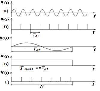
In the "frequency ratio" higher frequency voltage is applied to the input of "1" (the key position on the switch to "1" in Fig. 1).In the channel voltage is converted into a sequence of short pulses with a repetition rate equal to ƒ; c1. These pulses are fed to a first input selector temporary, at its second input receives a control pulse of duration T c2. Formation of the control pulse occurs in the channel 2 of the signal with lower frequency ƒ; c2, applied to the input 2. Change of frequency division in block 9 can increase the measurement time, which, in turn, increases the ability of integrating ESCH. In Fig. 4. ESCH illustrated work in measure mode frequency ratio ƒ; c1 / ƒ; c2. The figure shows that the N · T c1 = n · T c2 from
counting time
The error of measuring the ratio of the frequency ƒ; c1 / ƒ; c2 consists of two components: a conversion error (δ conv) and comparison (δ N)
where n – the multiplier period U c2 – the voltage signal applied to input 2, U f – noise voltage. The absolute error of discreteness
The relative error in discrete
where The total error is given by
Position the decimal point is determined by the degree of a series of numbers expressing the multiplier period n (n = 10 0, 10 1February 10, March 10, April 10). Consider the example of measuring the ratio of the frequencies from the same positions as before, ie minimize the error. Example. Let the frequency ratio measured 2.1 MHz / 3 kHz frequency meter H3-57. Solution. Write according to (16) equation:
where Т с2 = 1/ ƒ;с2 = similar to Т с1 = then whence
Take n = 10, 4:
Determine the absolute error of discreteness
Calculate the relative error
where The result on the scoreboard 700.0000.
|
 ;
;


 .
.

 ,
,
 .
. .
.
 =
=  ;
; ;
; ,
, .
. 
 = 3,33 s.
 .
.
 ,
,
 ,
,  .
.