Combined axial tension (compression) and bending
The beam is represented in Fig. 7.3 which is subject to the combined action of bending and axial tension. The transverse load causing bending can also be more complicated. To determine the sum stresses the principle of the superposition is applied. The tension stresses of the force F1 at all points of the cross section, as it is well known, are equal, they are determined by the formula
Fig. 7.3.
or in a general case (under any axial load) by the formula
where
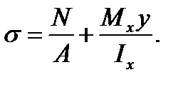
Hence, the sum stresses at any point are
In the given case the section is dangerous at the rigidly clamped end where the maximum bending moment acts and is equal
For the bars equally working in tension and compression the strength conditions are as follows
If the transverse load is complicated to determine the danger section and the maximum bending moment it is necessary to draw first the bending moment diagram. The received relations are also correct under the action of the compression force but the stress In the case of tension and unsymmetrical bending the stresses are determined by the formula
For bars from the materials equally working in tension and compression with the cross section having the angle points equidistant from the principal x and y -axis (the rectangular type, the double - T profile and the like) the strength condition has the form
For the bars manufactured from materials differently working in tension and compression the strength checking must be performed both by tension and compression stresses.
|
 , (7.15)

 is the normal force at the section considered. The bending stresses according to the formula
 (7.16)
 At this section the more loaded points will be the ones which are located along the line AB because at them the stresses in tension and the most stresses in bending are added up (
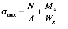 ). At the point along the line DC stresses will be lesser:
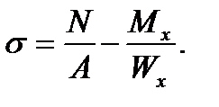 (7.17)
 (7.18)
 will be negative and the most (by absolute value) stresses will be at the points along the line DC. It is necessary to note that under the action of the compression force the above given formulas are correct only for the bars of the large rigidity, i.e. those whose axial compression force influence upon the deformation of bending is insignificant and may not be considered.
 (7.19)
 (7.20)