Combined torsion and bending
The bar represented in Fig. 7.5 is subject to torsion and bending. The details of the machine-building constructions subject to torsion and bending occur very frequently. Typical example of such details is the shafts of different machines. Let us begin with applying the principle of superposition and determine separately the stresses setting up in the beam in torsion and apart from it at the beam cross sections, the normal stresses set up achieving the maximum value on the extreme beam fiber: In the case represented in Fig. 7.5 the section with the maximum bending moment coincides with the section where the maximum twisting moment arises. This section is at the rigidly clamped end. The points C and B of this section are dangerous. Consider the stress state at the point C. The maximum shearing stresses in torsion arise at the cross section area passing through this point On the area of the longitudinal section the normal stresses are missing but the shearing stresses have the same value as that at the cross section.
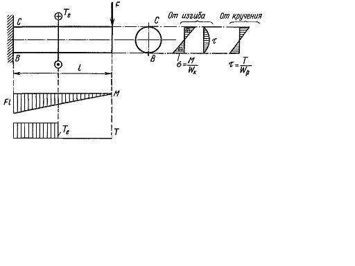
Fig. 7.5.
Fig. 7.6.
As the stress state is biaxial, to check that stress we apply we use one of the stress hypothesis. Keeping in mind that the shafts are manufactured from steel, we apply the third or fourth stress hypothesis. For this principal stresses must be determined for the given stress state (Fig. 7.6). The principal stresses are determined by the known formula
The strength condition is determined according to the third hypothesis (the hypothesis of the maximum shearing stresses)
Substituting the values
Considering
From this we receive the relation for the section selection (the design calculation)
Remember that if the shaft suffers bending in two mutually perpendicular planes, then
The strength condition for the case of the plane stress state according to the fourth strength hypothesis (the maximum energy of distortion hypothesis) is as follows
Substituting the values
but
From this for the section selection we have
|
 and the shearing stresses achieving their maximum on the neutral axis. The shearing stresses at the cross sections setting up from torsion achieve their maximum value at the points of the section outline:
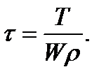
 and the maximum (in the given case stretching) normal stresses from bending are

 (7.28)
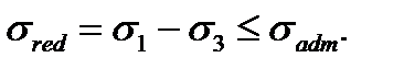
 and
and  we get
 (7.29)
 and
and  we get
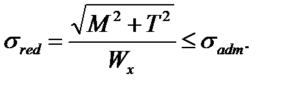 (7.30)
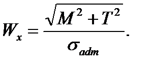 (7.31)
 (7.32)
 (7.33)
 and
and  expressed by
  and
and  for the shaft cross section into this relation we get
 (7.34)
 and
and  hence
hence (7.35)
 (7.36)