Key statements
2.1 EFC verifiable characteristics. Subject to verification are the following parameters: - the range of measured frequency sinusoidal and pulse signals -the error of measuring the frequency -the frequency range in the measurement period, sinusoidal and pulse signals -the period of measurement error -the measuring range of the frequency ratio -error measuring ratio of frequencies, etc. 2.2 Means of measurements used for calibration. When checking EFC, the following reference and auxiliary means of verification: - receiver reference frequencies - rubidium frequency standards with nominal values of the frequencies of 100 kHz, 1 and 5 MHz with the relative instability of 10-11- - quartz-crystal generator with the same values of nominal frequency and the relative instability of the order of 10-8 - frequency standards and quartz-crystal generators are measures of the standard frequency, and if there is a possibility and necessity, the accuracy of these measures is controlled by the receiver reference frequencies - frequency synthesizers, covering the frequency range 0.01 Hz -50 MHz - Frequency Multipliers - Frequency Comparators - universal generators, voltmeters, oscilloscopes, and AC voltage. 2.3 Conditions of verification and preparation for it. In carrying out verification operations subject to the following conditions: - the unit that came in fact, subjected to external examination. We should pay attention to the availability, serviceability and cleanliness of the entire property, the condition of paint and clear labeling. The presence of dirt and rust is unacceptable. The instrument must not be mechanical damage that could affect its operation, such as looseness of control knobs, damaged terminals, poor fixation switches - devices having a fault, in actual fact are not accepted. - Verification of device parameters is performed at a nominal supply voltage under normal conditions: - ambient temperature is 293 ± 5 ° K (20 ± 5 ° C) - Relative humidity of 65 ±15%, atmospheric pressure is 100 ± 4 kN / m2 (750 ± 30 mm. Hg. Art.) - Voltage Mains 220 V ± 4,4 V. Before the operations of checking, you must make the following preparations: - place the unit under verification in the workplace, providing comfort and eliminating getting it out of direct - connect wire terminals that are under verification and reference devices used for verification, to the ground bus, - to make a connection, the device under verification to model devices with regular cables and adapters; - connect devices to an AC voltage of 220, 50Hz - plug-in devices to the network and give them a warm-energized for 1 hour. 2.4 Transactions verification. Visual inspection When conducting an external examination must be verified: the ● absence of mechanical damage, affecting the accuracy of the readings, the ● presence and strength of attachment of controls and switching, the clarity of fixing their positions, smooth rotation of knobs settings; ● arrows showing the correct installation of devices against the zero marks of the scale, ● the purity of sockets, connectors and terminals ● the state of wires, cables, adapters, ● paint condition and clarity of markings ● the absence of detached or weakly attached circuit elements and foreign objects (defined by ear when bending device). If the appliance defects, due verification shall be cancelled and direction for repair. Testing Verifying the device in the "Self-control" mode on the device control frequencies. Calibration range of measured frequencies and periods of Verification range of measured frequencies and periods is carried out according to the scheme shown in Fig. 1, by direct measurement of the frequency (period), given by the measuring generators (MG) of the respective ranges and types. Measurements were carried out at both ends of the range of frequencies f n (Tn) and f in (Ts) and 5- 6 points within range. If necessary, check the minimum values of the input voltage to the output of the generator voltmeter connected by means of which, and establish the minimum voltage input signal. At the same time observed EFC has to have stable results.
The basic definition of the relative error of frequency measurement is performed according to the expression:
where δqg – the relative error of the reference oscillator, T count – measurement time (time accounts); f s – measured frequency.
Determining the relative error of the measurement period is made according to the
where T qg – the period of the reference oscillator signal, Tc – as measured by the period; n = 10ν, ν = 0, 1, 2, 3, 4,.... – a multiplier signal period; m = 10ε ε,= 0, 1, 2, 3, 4,.... – frequency multiplier of crystal oscillator.
In determining the errors of δ f and δ T is checked separately: - the relative error of the reference frequency crystal oscillator (δqg) - components of the measurement error due to the frequency and period of discontinuity (the second terms in equations (1) and 2)).
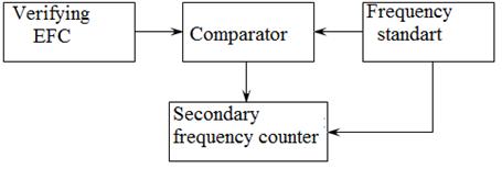
Determination of the relative error by the reference frequency of quartz-crystal generator Relative accuracy of the reference oscillator frequency is determined by comparison with the comparator circuit shown in Fig. 2.
Output of the reference oscillator under verification EFC connected to the input of a comparator. Frequency of the source model, which is the standard rate n1-type, the signal of the same frequency at the input of the comparator 2 and the connector "5 MHz" frequency of type H3, which uses this signal instead of its own reference clock signal. And the comparator output signal frequency f t is input auxiliary EFC, operating in the frequency measurements at a measurement time of 1 or 10 sec. To improve the reliability of measurement results is removed at least 10 consecutive readings of the frequency and is their average value:
where fci – a frequency output of the comparator unit of measurement; n – the number of single measurements carried out.
Relative error of the reference oscillator frequency is determined by the
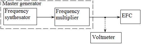
where f c – value of the frequency comparator corresponding to the nominal value of the reference frequency generator; f n – nominal frequency of the reference oscillator. Appendix B shows the NMC frequency standardЧ1-53, the frequency comparator Ч7-12 and frequency synthesizer. In carrying out laboratory work rather than the above model can be used similar devices on the NMC devices. Determining the relative error δqg, shall adjust the frequency of the reference oscillator EFC, after which the slot "frequency correction" sealed. Determination of components of the error of the measured frequency and period due to the discreteness of the account Definition data components of the error is carried out by direct measurement of the standard frequency. The source of the reference frequency is used, or a frequency synthesizer or synthesizer with frequency multiplier. Circuit connection of devices with the operation of verification is given in Figure3. The synthesizer must be synchronized with verifiable EFC from the reference oscillator device under verification. The input signal is fed under verification EFC, close to the upper limit frequency and a voltage equal to the minimum input voltage at which the EFC should work fine. In the absence of a graded synthesizer voltage output signal, it is necessary to control the voltage with a voltmeter. Carry out a series of 10 observations. The results of calibration are considered positive if the 9 cases (reading) the measurement does not differ from f qg more than ± 1 division accounts.
For a similar procedure is determined by the component of error due to the discreteness of the measurement period. In this case the input frequency is served frequencies corresponding to the upper and lower frequency range specified for the frequency measurement mode period.
|


 ,
,
 ,
,
 ;
; ,
,
 ,
,
 ,
,
 ,
,


