Installation
A universal machine to test materials
To conduct a test special machines and universal electrically driven gear-type or hydraulic machines can be used. A universal machine of the 1958Y-10-1 type is used in this laboratory work. This machine consists of two units: a loading device, a loading and measuring controlling unit (Fig.5). The loading device consists of a rigid frame, a traveling cross-bar and two grips for a specimen. The displacement of the traveling cross-bar is realized by the electric motor and worm-gearing. On the face panel there are two information boards which indicate the current value of the load and the displacement of the active grip. Here there are also installed cross-bar controlling buttons and the speed pointer. The latter is connected with the reduction gear. They ensure the displacement of the active grip in the 0,005+500 mm/min range of velocities. The indicators give information about the condition of the testing machine.
Test specimens
The metal specimens used for the axial tension have either a round or a rectangular section. The dimensions and production standards of the specimens are given in GOST 1497-84. The specific features of the specimens are strengthened places to be installed in the grips of the testing machine, and the gradual change of sections. While producing specimen from blank parts, certain precautionary measures are taken to exclude any changes of metal properties caused by heating or hardening. To determine the degree of change of the gage length after the rupture, certain hachures are marked by a dividing machine on the testing surface in every 10 mm all along the length. The main dimensions of cylindrical specimens are shown in Fig.6 and their values from GOST 1497-84 are given in the table 1.
Fig. 6. Types of proportional cylindrical specimens for tensile test (GOST 1497-84)
Order 1. Study the basic theoretical statements and the conditions to conduct the tensile test, testing machine and specimens. 2. Prepare the testing machine for work: switch on the main switch in the power cabinet, switch on the packet-type switch of the loading apparatus and the controlling unit, switch on the button "POWER", fill the diagram registration unit with the ink and insert a diagram form. All this is done by the teaching-foreman. 3. Choose a specimen you need from table 1 (№7). 4. Place the travelling cross-bar so as you can insert a specimen in the grips. For this you have to press the button "START", then press the button "UP" or "DOWN" depending on the required movement direction of the cross-bar. At the right position of the cross-bar press the button "STOP". 5. Insert the specimen into the grips of the loading unit and cramp it. 6. To eliminate the clearances, apply the initial load of 1,0 kN by pressing the buttons "START", "DOWN", "STOP" in a sequence. 7. Put the zero values on the indicator panel "LOAD" and "DISPLACEMENT" by pressing the buttons "TESTING REGIMES". 8. Conduct the specimen test up to the rupture by pressing the buttons "START" and "DOWN" in sequence. After the rupture of the specimen press the button "STOP". In the process of testing watch the indicator and the diagram registration. 9. Write down the last value on the indicator panel "LOAD" - Fut. 10. Print the diagram "F~ΔL " (Fig.4). 11. Draw the diagram " 12.1 By the diagram " Determine the modulus of the extension elasticity from the diagram "
12.2. Determine the proportional limit
Fig.6. Graphical way to determine the proportionality limit.
12.3. Determine the elastic limit
Fig.7. Graphical way to determine the elastic limit
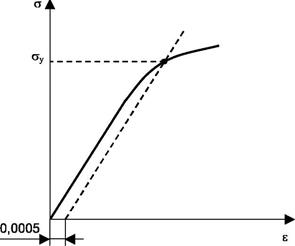
12.4. Determine the yield point
Fig.8. Graphical way to determine the yield point
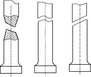
12.5. The breaking strength 12.6. Determine the nature of the specimen rupture. The typical specimen ruptures of different materials are shown in Fig.9.
а) b) c)
Fig 9. Types of specimen ruptures in tension: a - necking rupture (low-carbon steel); b - rupture by separation (cast iron); c - rupture by cut-off (aluminum alloys magnesium strained)
12.7. Determine the plasticity characteristics. The relative elongation of the specimen, broken in the middle part of the gage length, is determined by the specimen gage length, marked symmetrically to the middle part before risks testing, and by the total elongation, which is measured after the rupture upon caused risks, as the difference L-L0 (Fig.10). To receive the correlate results in the time of the specimen rupture at the end regions of the gage length, equal sections are drawn in 10 mm, and ΔL is determined supposing that the rupture has taken place in the middle part. The measured length of the gage length has to be calculated from the relation:
L=bc+cf, bc=ab+ac
where ab is the length of the region from the rupture place of the extreme mark b to the direction of the short mark until the mark c; cf is the length of the region from the mark c to the rupture direction of e mark, constituting as many sections as there are in the region from the mark c to the extreme mark f (to the end B). The percentage of elongation is determined by the formula
Fig.10. Determining the percentage of elongation and reduction
The reduction in the area of a cylindrical specimen can be determined using the middle value of the diameter in the rupture place, calculated in two mutually perpendicular directions. In the case of testing the plate specimens (GOST 1497-84), as a rule, it is not recommended to determine the value of the reduction in the area. If it is necessary to determine The percentage reduction in the area after breaking is determined by the formula
12.8. Determine the grade of the material by the results of virtual testing from table 2, taken from the handbook of materials.
Report The report must include: 1. The title page. 2. The goal of the work. 3. The description of equipment and specimens. 4. Tension diagram and its processing. 5. The testing results.
6. Test questions answered. 7. Conclusion.
|

 Fig.5. Universal machine of the 1958Y-10-1 type to test materials

 " (Fig.4) in a corresponding scale.
 (MPa)
(MPa) from the diagram "
 . On the ‘
  ’ axis measure off the residual deformation
 (yield strength
  ). On the “
 is the maximum value on the "


 area of the cross-section area АК in the rupture place, it can determined by multiplication of the maximum length of the specimen in the rupture place m and the minimum thickness n.


